Unified Tow Brake Towed Vehicle Kit (TVH-1000K)
Operating and Installation
Instructions
Installation instructions for motor coaches pre-wired
and towed vehicles equipped with electric hydro-boost power brakes
READ THIS MANUAL BEFORE ATTEMPTING
TO INSTALL UNIFIED TOW BRAKE.
It is the responsibility of the towed vehicle owner to determine under what conditions, if any, the towed vehicle may be towed.
PLEASE REGISTER PURCHASE OF
UNIT
BY SENDING REGISTRATION CARD TO U.S. GEAR CORP.
Serial # _____________________
Form IS-6000TVH (2/09)
D-Celerator? Unified Tow Brake Operating Instructions
CAUTION: The Unified Tow Brake was designed to enable your towed vehicle brakes to assist your motorhome brakes. Under no circumstances should the tow brake be used to replace your motorhome brakes.
Connections Between the Motorhome and the Towed Vehicle
Two connections between the coach and the towed vehicle must be completed before operating the Unified Tow Brake.
First, plug the wiring umbilical harness connectors to the mating connectors at the rear of the motorhome and the front of the towed vehicle. This harness contains wiring to supply a charge to the towed vehicle, and to carry the braking signal to the power module. Make sure the motorhome can make sharp right and left turns without strain on the umbilical cord.
Also, the lanyard from the breakaway switch on the towed vehicle must be attached to the rear of the motorhome. In a breakaway situation, the switch will activate full braking in the towed vehicle. There should be no obstacles or strain on the lanyard cable to the motorhome. Also, make sure the motorhome can make sharp right and left turns without strain on the lanyard cable. Be certain that the breakaway switch is allowed to swivel so that the switch is always in a straight line with the lanyard. Do not let lanyard cable drag on the ground. Fasten lanyard to motorhome frame ? not on safety chains, tow ball, or towing hitch system.
If the towed vehicle is equipped with adjustable pedal assemblies, the brake pedal assembly should be adjusted closest to the driver seat when towing. Check to be sure the brake lamps are not illuminated. If the Unified Tow Brake has been installed correctly, the brake lamps should not be illuminated.
Any time you are driving your towed vehicle, the harness and the lanyard should be completely removed from both vehicles and stored in a secure location. An additional pin is provided in the kit on a key ring to place in the breakaway switch to release your towed vehicle?s brakes. This pin is simply a convenience for you so that you don?t have to leave the lanyard pin in the switch with the cable rolled up when you are driving your towed vehicle.
Inside the Motorhome
The light bar on the remote control serves several purposes:
? When the wiring between the motorhome and the towed vehicle is connected and the circuit is complete, the green LED will illuminate. NOTE: The green LED must be illuminated when the Tow Brake is in use. If the green light is not on, the tow brake is not functioning.
? The series of red LEDs indicates the amount of brake effort being applied in the towed vehicle. These lights are activated whenever a braking instruction is sent to the towed vehicle (when motorhome brakes are applied or when the manual override lever is depressed).
? Finally, if the good wiring connection between the coach and the towed vehicle is lost, the green light will go out and a beep will be emitted from the controller.
You will also get a beep from the controller if the towed vehicle brakes are applied without a signal from the controller. If you hear the beep, pull off the road and stop as quickly as possible.
When you depress the brake pedal in the motorhome the Unified Tow Brake automatically activates the brakes in the towed vehicle. The amount of proportional braking in the towed vehicle is easily adjusted using the gain knob on the top of the remote controller.
Setting the gain level is like setting the gain on electric trailer brakes. We recommend initially setting the gain level at the mid-point of 5, which allows the towed vehicle brakes to mirror the braking action of the motorhome. With a lower gain setting, you will have less aggressive braking from the towed vehicle. With a higher gain setting, you will experience more aggressive braking effort in your towed vehicle. Set the gain knob to the setting that gives you the brake effect you like. The numeric indicators on the gain control knob will assist you if you would like to have different settings for different driving conditions. When your driving conditions change, you could then quickly set the gain knob to your previously selected location.
The manual thumb lever on the remote control allows you to activate the brakes in the towed vehicle without applying brakes in the Motorhome.
Before driving your motorhome using the Unified Tow Brake, be sure that all wiring harness connections and breakaway switch lanyard between the two vehicles are attached and are secured so that neither is allowed to drag the ground or is pulled/stretched when making a hard left or right turn. Place the ignition switch in the towed vehicle in its normal position for towing which unlocks the steering wheel.
| Test the Breakaway Switch on a Regular
Basis and Make Sure the Lanyard Cable Is Not Damaged When testing the switch, disconnect umbilical cord from towed vehicle. Pull lanyard pin out of the breakaway switch. This will take approximately 20 lbs. of pull. The brake pedal will be activated. When test is completed be sure back of lanyard pin is flush with the switch. The black washer should disappear. Reconnect umbilical cord to motorhome. NOTE: To prolong the life of the switch, we recommend spraying electrical contact cleaner once a moth into the hole on the switch where the lanyard pin is inserted. |
D-Celerator
? Unified Tow Brake Installation ManualINSIDE THE TOWED VEHICLE
|
This INSIDE THE TOWED VEHICLE Section is for
Serial Numbers 017185 AND HIGHER (for other serial numbers, see below) 1. Locate an area to place the solenoid assembly. The primary consideration in placing the solenoid is that it is out of the way when driving the towed vehicle. A secondary consideration is that the solenoid is hidden from view. In most installations the preferred location is high on the floorboard under the dash and under the carpeting on the passenger side, but practically any location is acceptable (for example, under the driver?s seat, beside the driver?s seat, behind the driver?s seat, in front of the driver?s seat, under the passenger seat, under the back seat, in the trunk) as long as you have sufficient cable to reach the brake pedal from the solenoid. The cable assembly included in the kit is 4? long. Longer cable assemblies are available. If you prefer an 8? (part # CA-6081) or 12? (part # CA-6121) cable assembly, you may order them from your selling dealer. The solenoid does NOT have to be in a straight line with the brake pedal. Be sure that the solenoid, and all the components of the Unified Tow Brake are out of the way for driving the towed vehicle after it has been separated from the motorhome. 2. Install the jam nut (#23) and solenoid end (#22) on to the threaded rod of the solenoid. 3. Route the cable (cylinder end) to the solenoid and push the cylinder through the hole at the end of the solenoid plate. Center the small cylinder at the end of the cable in the solenoid end and place the inner cable into the slot in the solenoid end.
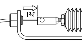
5. Adjust the pull of the solenoid. Pull the plunger all the way back and measure from the end of the solenoid end to the face of the cable retainer. The measurement (gap) must be exactly 1-3/8". (See Fig. 1) The Unified Tow Brake will not function properly if the 1-3/8" measurement is exceeded. 6. Use the 1/4" x 1" self tapping screw to anchor the solenoid so that it does not move around the passenger compartment of the towed vehicle.
7. Pull the carpet up to expose the insulation on the floorboard of the driver side. Remove the rocker panel if necessary to gain access to the edge of the carpet.
9. Establish a location for mounting the pulley, but do not attach the pulley. NOTE: Be sure the brake pedal will not make contact with the pulley when full braking is applied to the pedal. Move the pulley bracket to the left or right on the firewall to avoid contact with the brake pedal. 10. Slit the carpet under the dash just behind the location of the pulley to provide an opening for the cable to enter. 11. Guide the cable assembly through the slit in the carpet in front of the solenoid and up through the slit behind the pulley location. 12. Place the brake pedal end of the cable in the slot on the side of the brake pedal bracket and screw the threaded ferrule into the brake pedal bracket. 13. Mount the pulley system in the location you determined in step 6 against the inside of the firewall behind the brake pedal. To mount the pulley you will need to "straddle" the inner cable with the pulley bracket with the pulley pin hole on the side farthest from the stop bracket. Then attach the pulley using the four self-tapping sheet metal screws supplied. Before fastening the screws, be sure there are no vehicle components on the engine side of the firewall which could be damaged by the screws (booster, brake line, etc.). Insert the pulley pin through the hole in the pulley bracket and secure with the pin clip. 14. Be sure to leave approximately 1/4" of slack in the inner cable. Then mount the outer cable support bracket in a location which is in a straight line with the pulley. The outer cable support bracket can be at any length below the pulley. The way to determine its proper location is to slide the bracket over the ferrule at the end of the outer cable until the ferrule bottoms out in the hole of the support bracket. Tighten the #5 Allen set screw snug against the ferrule on the end of the outer cable in the support bracket. 15. Determine the layout of the cable assembly on the floorboard or firewall. The cable assembly can be routed across the floorboard to compensate for any excess length. You may curve or loop the cable assembly with a big, sweeping radius, but be sure not to have any tight radius curves or loops in the cable which would cause the cable assembly to bind or hang up when the tow brake is being used. 16. Once you have determined the layout of the cable assembly, score the insulation and place the cable in the slot to allow the cable to lay flat on the floorboard. 17. Lay the Power Module under the dash out of the way. The Power Module will be secured under the dash at the end of the installation procedure using wire ties. Leave the carpet pulled back and the rocker panel exposed until installation is completed. 18. Once these connections have been completed in the towed vehicle, check to make sure that the brake pedal is in a completely relaxed position when the system is not in use. One way to double check is to make sure that the towed vehicle?s brake lights are not lit. If necessary, make fine adjustments to the inner cable using the threaded ferrule you have screwed into the brake pedal bracket.
|
This INSIDE THE TOWED VEHICLE Section is for Serial
Numbers 017184 AND LOWER (for other serial numbers, see above)
|
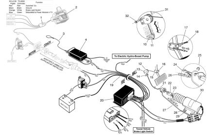
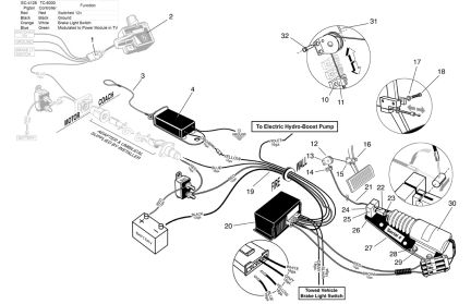
UNDER THE HOOD OF THE TOWED VEHICLE
The violet wire used in towed vehicles with vacuum assist power brakes is not used in towed vehicles with electric hydro-boost brakes, except in the H3 Hummer and Toyota 4Runner, Highlander, and FJ Cruiser. Refer to the installation supplements for those towed vehicles.
1. Mount breakaway switch on horizontal plane of the towed vehicle frame. There should be no obstacles or strain on the lanyard cable to the motorhome. Also, make sure the motorhome can make sharp right and left turns without strain on the lanyard cable.
2. The breakaway should be bolted to the frame with 1/4" bolt that will allow the switch to swivel. Be certain that the breakaway switch is allowed to swivel so that the switch is always in a straight line with the lanyard.
3. Do not let lanyard cable drag on the ground. Fasten lanyard to motorhome frame ? not on safety chains, tow ball, or the towing hitch system.
4. Mount the 40 amp Circuit Breaker close to the battery with the two screws supplied.
5. Following the wiring details in the middle of this booklet attach the Harness and Wires under the hood of the towed vehicle.
NOTES on Wiring (refer to Component List in the middle of this booklet):
a) The red 12 gauge wire is the 12 volt power wire. IMPORTANT: Be sure to leave the red wire that runs from the "battery" side of the circuit breaker to the "positive" post of the battery unconnected until the rest of the installation of the Unified Tow Brake is complete.
b) For easier installation, the blue and yellow 18 gauge wires which plug into the four position connector are are not installed into the connector before shipping. Run the blue and yellow 18 gauge wires from the engine compartment through the firewall and insert the metal terminals into the connector with the white and gray wires as shown in the component rendering in the center of the booklet. Be sure the wires are seated properly in the connector. Note: Once the wires are inserted into the connector, they will not come back out.
c) If towed vehicle has been wired for auxiliary lights, or when the towed vehicle was wired for towing you know for sure that blocking diodes were added to protect feedback from the towed vehicles? brake lamps, the action described in this paragraph is not necessary. If the motor home lamps are tied into the factory towed car brake lamps, and NO blocking diodes are installed, complete the following step. Locate the towed vehicle?s brake light switch. It may have several wires. With the ignition in the "ON" position, use a test light to find the 12 volt supply wire that feeds power to the switch at all times. (This is the only wire that is "hot" in all cases.) Cut the 12 volt power wire and attach the gray and white wires to the two ends of the wire with the butt connectors supplied. It doesn?t matter which of the two wires is connected to which end of the power wire. This action will deactivate the brake light switch when the Unified Tow Brake is armed.
d) The black 12 gauge wire (Power Module ground) and the blue 16 gauge wire (Breakaway Switch ground) are separate from the harness. For the Breakaway Switch ground wire, be sure to scrape down to bare metal in the area of your ground screw on the vehicle body before attaching the ground wire. The Power Module ground wire must be grounded to the negative post of the towed vehicle battery.
e) The Power Module ground (12 ga. black), the Electric Solenoid wire (12ga. brown), and the Solenoid wire (12 ga. red) all attach to the front of the Power Module.
e) The Power Module ground (12 ga. black), the Electric Solenoid wire (12ga. brown), and the Vacuum Pump/Solenoid wire (16 ga. violet/12 ga. red) all attach to the front of the Power Module.
CONNECTING MOTORHOME AND TOWED VEHICLE
Installer must supply:
1. Six-wire umbilical with six-pin connector on one end and seven-pin
connector on the other
2. Six-pin connector for towed vehicle
Refer to the illustrations below to connect the motorhome and towed vehicle. Attach the blue (signal) wire from the towed vehicle harness to the ?A? (Center) position on the connector. Attach the red (power) wire from the towed vehicle harness to the ?S? position on the connector.
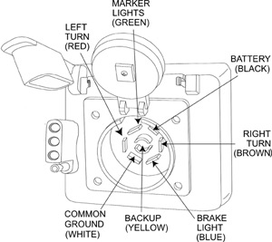 Connector on Back of Motorhome |
NOTE: Confirm that the 12v charge line is indeed at pin position 1 o'clock (black wire) by using a 12v test light. Sometimes the 12v charge line is tied to the ignition power. You may need to turn on the ignition in the coach to get power at the rear connector. Once you have confirmed that the 12v charge line is in the correct position, you can wire the front of the towed vehicle as outlined in the schematic to the right. | 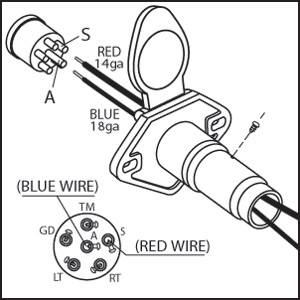 6-pin connector on front of towed vehicle |
COMPLETING CONNECTIONS IN TOWED VEHICLE
1. After connecting the towed car harness to the electric solenoid, route the harness along the rocker panel or under the carpet. Re-install carpet and rocker panel which were removed earlier in the installation.
2. Before using the Unified Tow Brake, attach the tow bar, safety chains, breakaway lanyard, and umbilical cord between the towed vehicle and the motorhome. Make sure the motorhome can make sharp right and left turns without strain on the umbilical cord or lanyard.
SYSTEM CHECK
After completing the installation and making all the wiring connections, perform the following tasks to ensure proper operation of the Unified Tow Brake.
After the breakaway switch has been installed and wired, slowly pull out pin and make sure brakes engage. Push the pin back into switch until the flange on the pin is against the switch and the black neoprene washer disappears. Do not leave the breakaway switch activated for more than 2-3 minutes at a time while testing.
With the ignition of the motorhome in the "ON" position,
1. the green light on the far right of the controller should be illuminated. This light indicates that the circuit is complete.
2. press down on the manual thumb lever on the controller. The brake pedal and the solenoid in the towed vehicle should move when the thumb lever is depressed. NOTE: The motorhome/towed vehicle combination must be in motion to check to see if the brake pedal in the towed vehicle moves when the brake pedal is depressed in the motorhome. The brake pedal in the towed vehicle will NOT move when you depress the brake pedal in the motorhome if the rig is stationary.
3. after test driving, check the brake lights on the towed vehicle to make sure they are off. This will confirm that the brake pedal is rebounding completely to an "off" position. (If brake lights in the towed vehicle are on, check for inner cable binding, or some other mechanical impediment which is causing the brake pedal to remain partially depressed when the brakes are released.)
4. unplug the umbilical cord. The green light on the controller should go out and a beep will be emitted from the controller. This indicates that the circuit is broken. (This result will also occur in a breakaway situation.)
After completing system check, be sure that all wiring harness connections and breakaway switch lanyard between the two vehicles are attached and are secured so that neither is allowed to drag the ground or is pulled/stretched when making a hard left or right turn.
Be sure to give the customer the spare breakaway switch pins, key ring, and the Customer Information Envelope which contains warranty registration card and warranty policy.
This completes the installation of the U.S. Gear D-Celerator? Unified Tow Brake.
|
|
|
|
Return to Unified Tow Brake Product Page
Return to Installation Page
 4.
Slip the inner cable down through the slot in the cable retainer (#24).
Push the non-hex end of the cable retainer through the hole in the
solenoid plate. Place the snap ring (#25) onto the cable retainer to
secure the cable retainer to the solenoid plate. Push the outer cable
into the hex end of the cable retainer. Then insert the hairpin clip
(#26) into the hole on the side of the cable retainer to secure the
outer cable to the cable retainer. Pull on the outer cable to make sure
that the cable is secured.
4.
Slip the inner cable down through the slot in the cable retainer (#24).
Push the non-hex end of the cable retainer through the hole in the
solenoid plate. Place the snap ring (#25) onto the cable retainer to
secure the cable retainer to the solenoid plate. Push the outer cable
into the hex end of the cable retainer. Then insert the hairpin clip
(#26) into the hole on the side of the cable retainer to secure the
outer cable to the cable retainer. Pull on the outer cable to make sure
that the cable is secured.
 8.
If the towed vehicle is equipped with adjustable pedals, install this
product with the brake pedal assembly adjusted closest to the driver
seat. After you have determined the location on the brake pedal bracket
which allows the 1?" stroke, place the mounting bracket on the brake
pedal and attach it using the two screws supplied. The mounting bracket
can be placed on either side of the brake pedal bracket. IMPORTANT:
Before securing the brake pedal bracket, project a vertical line from
the pivot point (it may not be possible to actually see the pivot) down
through the area that you are placing the brake pedal bracket. Then
place anything with a 90-degree corner on it (piece of cardboard,
triangle, etc.) on the top of the block and slide the backside
(vertical) to that imaginary line and tip the block up and down until it
lines up. It is important to pull the brake pedal at a 90-degree
angle from the pivot point to achieve maximum pull force from the
solenoid. (See Fig. 3)
8.
If the towed vehicle is equipped with adjustable pedals, install this
product with the brake pedal assembly adjusted closest to the driver
seat. After you have determined the location on the brake pedal bracket
which allows the 1?" stroke, place the mounting bracket on the brake
pedal and attach it using the two screws supplied. The mounting bracket
can be placed on either side of the brake pedal bracket. IMPORTANT:
Before securing the brake pedal bracket, project a vertical line from
the pivot point (it may not be possible to actually see the pivot) down
through the area that you are placing the brake pedal bracket. Then
place anything with a 90-degree corner on it (piece of cardboard,
triangle, etc.) on the top of the block and slide the backside
(vertical) to that imaginary line and tip the block up and down until it
lines up. It is important to pull the brake pedal at a 90-degree
angle from the pivot point to achieve maximum pull force from the
solenoid. (See Fig. 3)