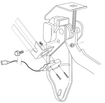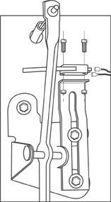
Fig. 1 --Example of mounting of
microswitch using universal bracket
D-CELERATOR?
INSTALLATION SUPPLEMENT
D-FEAT MICROSWITCH INSTALLATION
INSTRUCTIONS
(Kit # EC-4109K)
|
|
NOTE:
This microswitch is universal in design. It is intentionally designed to be used in a normally open or a normally closed position. You may install the microswitch as a D-Feat mechanism on any vehicle equipped with the D-Celerator? Diesel Exhaust Brake by simply adjusting the specific references to correspond to your application.A universal mounting bracket and proper fasteners are packaged with the D-Feat Microswitch. In many applications, the bracket offers superior mounting effectiveness compared to the tape also supplied with the microswitch.
The example below shows one option for mounting the bracket. There are almost unlimited mounting possibilities. Choose the most appropriate location, and you can easily bend or adjust the bracket to fit any application. Remember that the paddle (or wand) needs to rest on an object that moves with the throttle. Position the bracket and switch in a location that allows the switch to move freely.
Use extreme care when attaching to or near the throttle linkage, so that the possibility of binding or hindering the throttle linkage is eliminated.
Remember, the switch can be configured to either normally ?open? or normally ?closed? as outlined later in these instructions.
Specific Instructions for GM Duramax
|
|
1. The throttle assembly for the GM Duramax is illustrated in Fig. 2. Notice that there is a black plastic plate riveted to the throttle bracket. The black plate attaches the Accelerator Pedal Position Sensor (APPS) to the throttle bracket. (The throttle pedal lever is also attached to the bracket.) Three rivets secure the black pastic plate to the throttle bracket.
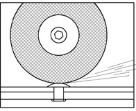
2. Grind the head of the middle rivet until you can see through the rivet (Fig. 3). CAUTION: Be sure not to grind down too far and cause the grinder to come into contact with the plastic plate.
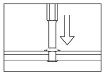
3. Use a drift to punch the remnants of the rivet out of the hole (Fig. 4).
4. Using snips, cut the long, slotted face of the microswitch bracket so that the bracket will fit over the angled edge of the throttle bracket assembly as shown in Fig. 2. NOTE: The flange-head bolt included with this kit should sit in the bottom of the slot of the microswitch bracket. If the bolt does not rest on the bottom of the slot, you will need to trim the excess of the slotted arm of the bracket.
5. Attach the microswitch bracket to the throttle assembly using the 5/8" flange-head bolt and nut supplied in the kit. Attach the the microswitch to the microswitch bracket as shown in Fig.2.
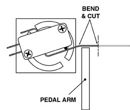
6. Bend the paddle lever of the microswitch so that the switch is open (paddle lever depressed) when the throttle is in a relaxed position. Snip the excess length of the paddle lever. (Fig. 5)
|
|
|
|
 Specific Instructions for Ford 6.0L
Power Stroke
Specific Instructions for Ford 6.0L
Power Stroke
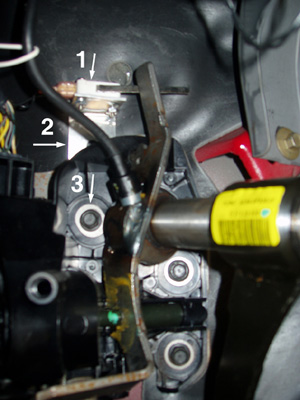
1. The throttle assembly for the Ford 6.0L Power Stroke is pictured at right. Using snips, cut the long, slotted face of the microswitch bracket (#2) just enough to open the bottom ?U? of the slot so that the bracket is open-ended.
2. Loosen top bolt of throttle assembly (#3) so that you can slide the microswitch bracket down and straddle the bolt between the throttle assembly and firewall. Position the microswitch bracket so that the short end of the bracket is near the top of the throttle lever. Re-tighten the top bolt of the throttle assembly.
3. Attach the microswitch (#1) to the microswitch bracket using the two screws and nuts supplied.
4. Bend the paddle lever of the microswitch so that the switch is open (paddle lever depressed) when the throttle is in a relaxed position.
Now continue with Testing Instructions below.
Connections
Referring to Figure 6, connect one of the spade connectors to the common post (#1). (The two wires have no polarity so it does not matter which spade connector is attached to which post.) This wire will supply power to the microswitch.
NOTE: For any application where the microswitch will normally be open (paddle lever depressed), place the spade connector on post #2. On applications where the normal position will be closed (paddle lever released), place the spade connector on post #3.
Attach the white Molex connector to its mate in the D-Celerator wiring harness.
Adjustments
It will be necessary to bend the paddle lever to adjust the microswitch. First,
disconnect the large red wire in the exhaust brake wiring harness from the
battery supply. This will prevent the D-Celerator
Testing
With the key on, and after the ECM has completed its cycle feature, make sure
the red light on the ECM is illuminated continuously. Depress the throttle pedal
and watch for the red light to start flashing. This indicates D-Feat mode.
Adjust the paddle lever, or re-position the microswitch if necessary, to allow
for the least pedal movement necessary to engage D-Feat mode.
Reconnect red wire to battery and test operation with a road test. CAUTION: To avoid tripping the circuit breaker, do not engage the solenoid more than 5 or 6 times per minute. If necessary, adjust the the microswitch until the brake will disengage with the slightest pedal movement.
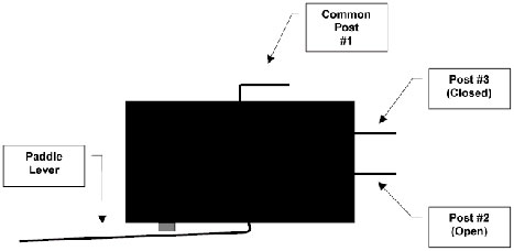
Fig. 6
Return to D-Feat Mechanism Installation Instructions Main Page
Return to D-Celerator Diesel Exhaust Brake Operating and Installation Instructions
Return to D-Celerator Product Page
Return to Installation Page